2001 Crystal Building Contest entry, class Freestyle/General
The Signal Sucker MkII
Charlie Cotterman, KA8OQF
The Signal Sucker MkII is a multi-purpose project for experimentation in the dark art of radio.
The Inspiration
Way back when, I was part of a public service demonstration put on by the Huber Heights (OH) Amateur Radio Club at the local library for the purpose of showing Amateur Radio to the area youngsters in particular. One demo was a board with nails in a circle, wrapped with wire, and a capacitor in the middle. A small generic AM/FM set was tuned to a locally empty frequency, then held in the middle of the coil. The cap was tuned, and suddenly what was later determined to be a 5kW AM station in Tennessee came swimming out of the static. This was in a reinforced concrete building in a hollow, 5’ below average terrain, mid-day in midsummer. Being of the SWL persuasion, I was impressed.
Further Inspiration
Recently having developed an interest in crystal sets (therefore becoming a denizen of three Web-based crystal forums and a fully-paid member of The Xtal Set Society), I had been consulting with (i.e. stealing every idea I could) from local crystal guru Ed Garner, WR8A. He gave me the basic recipe for what I called the Signal Sucker. After constructing it and adding a minor improvement, he looked at it and suggested adding a diode and ‘phones. Later that night, I did – and reinvented the wheel.
Construction Details
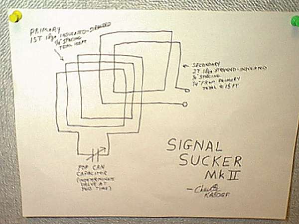
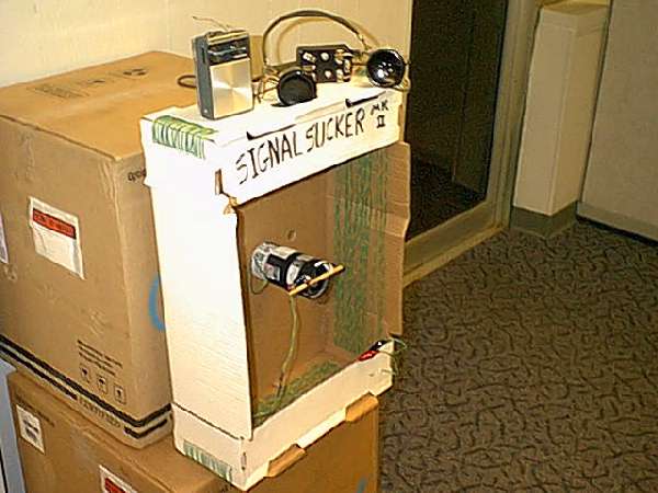
The Signal Sucker MkII is built on a produce box salvaged from the local grocery store. The cardboard box measures approximately 6”d x 15”w x 23”h. In the middle 4” of depth, holes were punched with an awl for the threading of two coils, both of 18ga insulated stranded wire. The primary coil is 15 turns spaced at Ľ”. The secondary coil (a pickup loop) is two turns spaced at Ľ”, and the secondary itself is spaced Ľ” from the last turn of the primary. A tuning capacitor made of pop cans and pop bottle plastic is across the primary for tuning (pop can stock is .004” aluminum, ‘rotor’ is approximately 11 sq in; dielectric is .015” polyethylene plastic from pop bottles; also used are liberal quantities of black tape and 6-32 nuts/bolts/washers/lock washers in the appropriate places to hold things together; design specs calculated from a capacitor design program in Hamcalc). The ends of the secondary coil have alligator clips on them for hookup to various items of equipment as detailed in the ‘Multiple Uses’ section.
Multiple Uses
The SSMkII’s origins come from the SSMkI, which had a standard 365pF broadcast cap for tuning, and no secondary coil. The MkII’s secondary coil was added for ease of use in experimentation with an old junkbox Radio Shack Patrolman Mini AM/VHF transistor radio. (With the MkI, proper orientation of the radio with the tuned coil was necessary for AM Dxing. With the addition of the secondary, ‘gator clipped to leads of a one-turn 22ga insulated wire loop around the radio’s ferrite bar antenna, orienting the radio inside the primary coil was no longer a concern.) The MkII’s effects on a transistor radio’s reception is nothing short of amazing. In one experiment, the radio pictured with the MkII clearly received CKLW (Windsor, Ontario, Canada) on Labor Day 2000, at high noon, inside a car, from Dayton OH. For instruction and demonstration purposes of radio propagation and theory of tuned circuits, the Signal Sucker MkII is a very good instructional tool. A copy of the MkI (with pop can tuning capacitor) was built by the author’s nephew (with suitable help with tools from Uncle Charlie) and entered in the grade school science fair. Naturally, Davion’s entry won it its age division, and was raved about by everyone in the class.
In addition, the MkII is the basis for a locals-only crystal set (statements from MRL literature indicate that an indoor loop of this general size is less than 10% as effective as an outdoor antenna with the same length of wire as in the loop). It can be an instructional tool as well, as an introduction to crystal sets.
The SSMkII is also a great detector for ‘fluorescent light buzz’, as it easily picks up the lights in the bathroom at home.
The MCFAD – the MultiConFigurable Audio Device
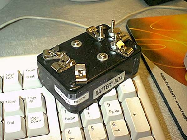
The MCFAD is built in a Radio Shack plastic project box (purchased as part of a bulk “Buy My Junkbox!!” deal on ebay) that measures approximately 1”d x 2”w x 3+” long. (This box is still stocked by Radio Shack).
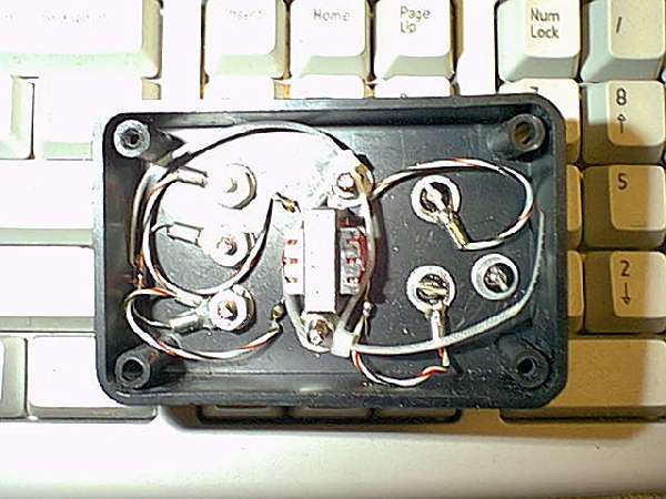
As can be seen in the pictures, there is liberal application of 6-32 hardware holding everything in, in addition of two small wire ties for extra security around the transformer. A small hand drill, soldering iron, screwdriver, nut driver, and some spade terminals were the only tools/parts needed for assembly. At a guess, there is less than $10 involved here (that includes the cost of the transformer). The layout was drawn, some parts were taped to the box to check for clearances (I’ve been told it’s lots of fun drilling into a transformer by accident), eyes were closed, a deep breath taken, and construction was begun. The project took about two hours to complete, including extra time for hands to stop shaking, triple-/fourple-/quintuple-checking layout and positioning, a smoke now and then, and a Pepsi. Now that I know what I’m doing (ho ho ho…), I could probably recreate this project in about twenty minutes.
The MCFAD is designed for use with HS-16A headphones – someone wishing to recreate this device for their own particular audio output choice may need a different transformer than the Mouser #TM-117. However, even if the size of the transformer requires a larger box, the general layout and construction would most likely remain extremely similar.
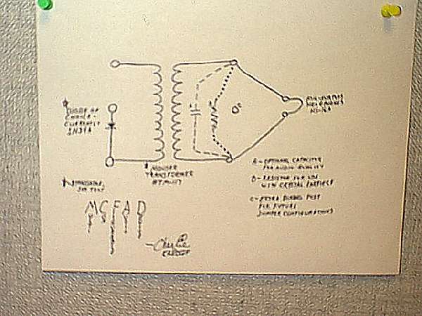
The MCFAD is designed to cover a multitude of possibilities in the crystal radio world. As seen in the schematic and pictures, there is a 1N34A diode in the box (easily replaceable, should I ever find one of those magic 12XXX series diodes everyone’s been raving about). The inputs to the MCFAD are Fahnestock clips. The input can be across the diode into the transformer, or not (if being used on a set that already has a diode installed). The MCFAD’s outputs are also Fahnestock clips to accommodate the pin tips on the HS-16A ‘phones. As visible in the photos, the bolts holding the output clips are installed long end out. This allows ‘gator clip jumpers to configure according to individual tastes. The output can have a capacitor in parallel (for audio quality) or a resistor in parallel (when using a crystal earpiece – this would mean jumpering from input to output bypassing the transformer, with or without diode as needed). I have an old junkbox resistor/capacitor substitution box which will be used during further experimentation along these lines.
A Thousand Words Make You Want Some Pictures
The photos of the Signal Sucker MkII show the coils and capacitor, the transistor radio used in funtime AM Dxing, and the MCFAD. There is no diode installed in the SSMkII itself; the diode is contained in the MCFAD. Note in its photos that the MCFAD is lying on a standard computer keyboard (shows how I spend my time at work, don’t it?). The scanner at work doesn’t, and the camera won’t quite do close-ups, so the unreadable scribbling is translated here, left to right on the schematic:
This leaves the SSMkII as a standalone unit, easily configurable (by clipping onto the leads of the secondary coil) for whatever the user has in mind; crystal set, interference hunting, DX booster, bookend, whatever. The SSMkII could also serve as the first tuned stage in a multi-stage crystal set. Note the mounting of the pop can cap, the weaving technique of the coils at the corners, and the custom nameplate of the SSMkII. As far as a schematic goes, details of the scribbling concerning the primary and secondary coils can be found in this document.
The Future
Post-contest modifications are envisioned. Further experimentation on the pop can cap is needed (haven’t quite found the right max/min values yet – the tuning range doesn’t go as low as I’d like, and things are crowded at the top of the AM band). A Russian mil-surplus tuning capacitor may be substituted for easier and more accurate tuning. An additional 2-turn loop may be added as the input loop from an external antenna for the multi-stage set drifting about in the deepest recesses of my devious little brain at this time.
The Public, and Dragging ‘Em In Kicking And Screaming
The Signal Sucker MkII is a great beginning experiment for kids. While the SSMkII only works on AM, imagine the wide eyes when suddenly their little dollar-two-ninety-eight personal Walkman is now the killer DX radio of the neighborhood. The difference between day and night reception can be examined also. And once they’re hooked by what just a coil and cap can do, now’s the time to spring it on ‘em – “Guess what – that thing can also work as a radio all by itself, without any batteries. Want to learn about that?”
Any kid with any sort of an imagination at all will find that invitation irresistible.