Skywave 2000
Designed and Built by Ken Harthun
| Greetings, Fellow Crystal Radio Enthusiasts! I present herewith my entry to this year’s Crystal Radio Building Contest. |
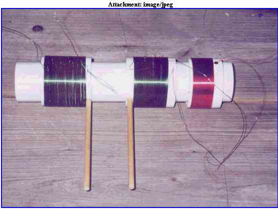
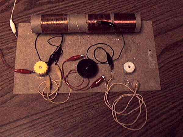
| My radio started out as an experimental breadboard using cardboard tubes, magnet wire salvaged from an old CRT yoke coil, polycaps salvaged from old transistor radios (and a couple of Radio Shack kits), alligator test leads, a diode and crystal earplug: |
 |
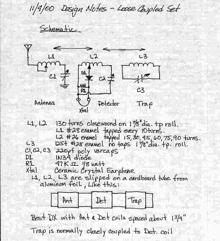 |
| One Friday evening, I was enjoying myself just testing out various circuit configurations and making notes on how they worked when some serious DX started coming in on the set. I quickly jotted down the circuit diagram and spent the rest of the evening logging DX stations while marveling that such a simple setup could perform so well. The circuit from that evening, with some minor changes, is the circuit I used. |
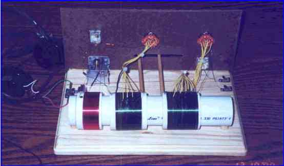
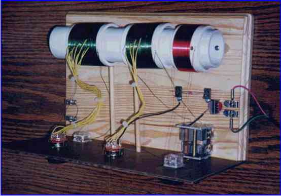
| The radio is a simple double-tuned loose coupler. The antenna tank is series-tuned with a polycap on the grounded side and adjustable coil taps. The detector tank is parallel-tuned and “floats”, i.e., there is no connection to ground. Taps on the detector allow me to achieve different selectivity/sensitivity settings. Because I live only 3 miles from a 50 Kw bandmaster, WSAI on 1530 KHz, I incorporated an inductively-coupled wave trap. Coupling to both the antenna and the trap can be adjusted, though trap coupling is normally kept very tight. |
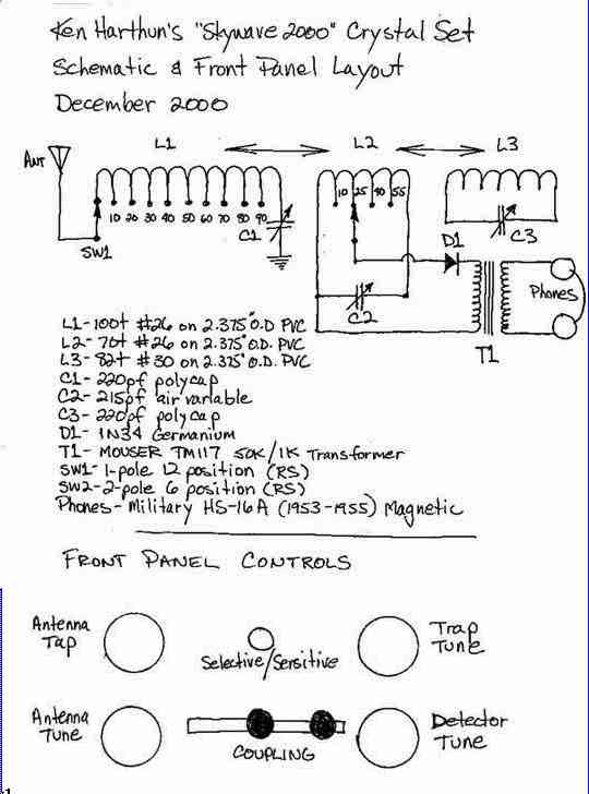 |
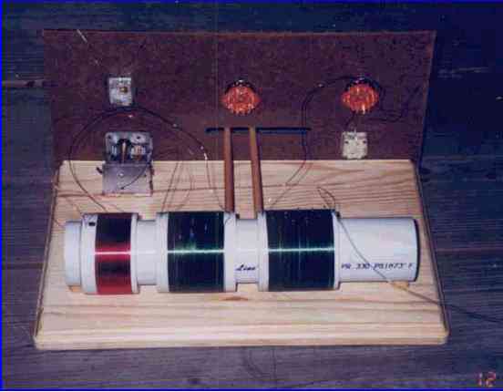
| There are no true vintage parts used in the set, unless you consider my 1953 HS-16A military headphones and the Fahnestock clips. The polycaps in the antenna and trap circuit were salvaged from a couple of radio kits. The detector variable is a three-turn ball-drive type salvaged from an old GE clock radio. 1.5” PVC was used as the rail to mount the 2” PVC coils so they would slide easily. An old clipboard was cut to size for the masonite front panel. Standard knobs from Radio Shack were used on the controls. |
| Several challenges presented themselves and were overcome. The first challenge was how to make shafts to attach knobs to the polycaps. I used Ľ” dowel material and notched the end to fit over the squared part of the shaft. This was super-glued in place and works very well. The coupling adjustment was next. I originally planned to use a rotary arrangement with an eccentric cam, but quickly found that to get the right amount of travel, the cam would be 6” in diameter and this just wouldn’t fit. So I settled on the dowel-and-knob arrangement you see in the pictures. It’s simple, and it works well while giving a good visual gauge of the coil spacing. |
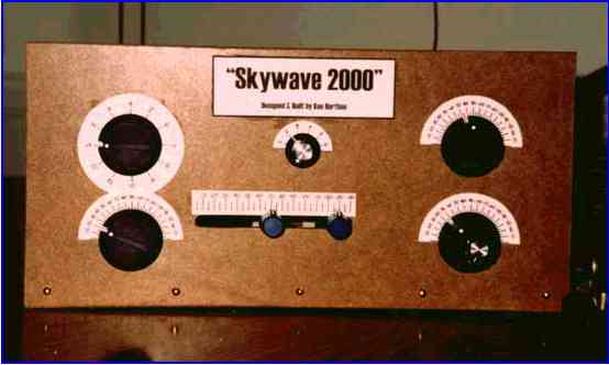 |
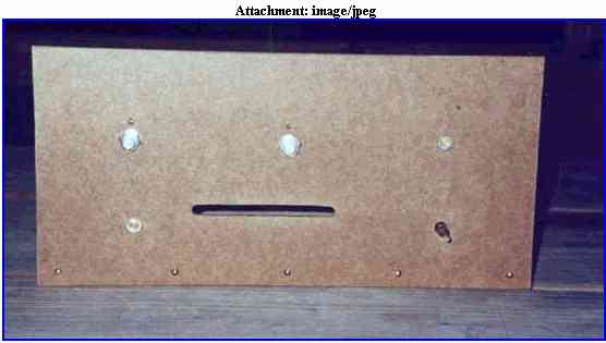
| The biggest challenge was the ball-drive capacitor. The drive shaft is 1/8” in diameter, while the main shaft is the standard Ľ”. You can see the shaft on the lower right in the photo below) If you look closely at the knobs in the finished set, you will see that I used two of them. I drilled a small hole in the larger knob (indicator) to pass the drive shaft. I then cut a small piece of Ľ” dowel to fit in the outer knob (drive), drilled it in the center and anchored it to the drive shaft. Turning the smaller knob drives the vernier and the larger knob indicates the position |
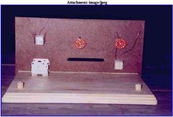
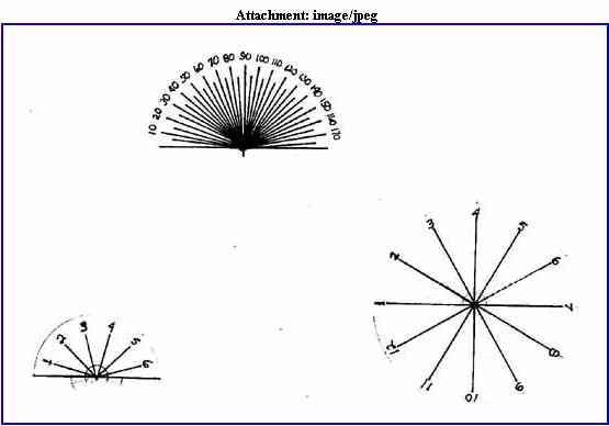
| In the tradition of many old-time radio builders, I decided to simply mount a front panel to a breadboard rather than build the set into a box. This gives it a kind of look that I have seen in many old articles and pictures. I gave some attention to layout in a symmetrical fashion for a nice appearance and chose my knobs accordingly. In true homebrew spirit, I decided against doing my dial indicators on my computer, pulled my old drafting tools out of the shed and made them myself. |
 |
| Operating the radio is actually simple despite all of the controls. I set the coupling to where the antenna coil is about 1.5” from the detector, set the antenna tap and capacitance to maximum and start tuning from the bottom of the band. I use the trap as needed. On close-in stations, I use the coupling controls and the detector tank tap switch to give me the best combination of sensitivity and selectivity. |
| The radio is a real performer on the air and works even better than the original prototype. As a matter of fact, WLAP on 630 in Lexington, Kentucky, 75 miles from me has gone from a DX station to one of my daytime “regulars” on this set. I have actually been able to effectively separate WNOP on 740 (local) from WSB on 750 in Atlanta. Though I could hear both, I was able to bring one up and push the other down using the coupling and selectivity controls. I estimate my actual “best” selectivity at around 25 – 30 KHz. |
| Longest DX so far has been WBAP on 820 in Fort Worth, Texas and CHMW on 840 in Santa Clara, Cuba. Most amazing DX was snagging WSEV on 930 from Sevierville, Tennessee near Gatlinburg. This station is over 250 miles from me and when I picked it up was on its nighttime power output of 148 watts! To date I have logged 32 stations in just a few hours of actual DX’ing. I can’t wait to do some serious listening! |
| You can see why I decided to call it the “Skywave 2000”! I’ve had some serious fun building this radio. |
| Good luck to everyone in the contest! See you in the clubs. |
|