Free Style Category, General Class
Submitted by Mark C. Roliff, AKA: sirmcr.
Introduction:
In the summer of 1957 one of my cousins received a crystal set kit for his birthday. His father helped him build it and get it working. (His father was renowned for having built the first radio in the township, sometime before 1920.) They installed the crystal radio near the boy's bed so he could listen at night without disturbing the rest of the family. I wanted one as soon as I saw it. All those coil taps, capacitors, and catwhiskers to tinker with!
I made my wishes known and at Christmas, I received a box of plans and parts. No crystal radio, this; it was a Knight Space Spanner and a pair of headphones. There were no coils to tinker with, just knobs. My brother helped me with the construction and I spent many nights tuning in the world on the shortwave bands.
Time passed and I took up Ham radio. I built a transmitter and transmatch and bought a surplus BC312. Alas, I found out that most hams are appliance operators; they buy all their equipment. They only tinker with antennas. Drat!
In 1986 I was reading a copy of Radio Electronics magazine and found plans for an "Old-Time Crystal Radio". The crystal juices began to flow again. The article went on the "to-do" stack and there it languished until last year when I struck The Crystal Set Society on the Internet. Out came the plans and I began to build the beast.
(with apologies to Lewis Carroll)
The article featured a loose-coupled unit with a single tank circuit. The building instructions were contradictory in places and the schematic diagram depicted components which could only be built by Lewis Carroll (the antenna coil has ten taps, but the coil switch is numbered 0 through 10).
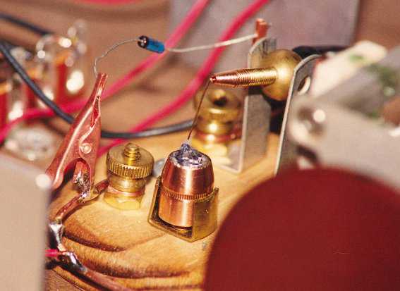
The detector stand is new. Its design is not the best; the shaft is threaded through the ball. The threads were originally very loose and intermittently resistive. I used a pair of dikes to mangle the threads enough to make a tight fit and good electrical connection. There is still backlash in the ball and shaft. I will make a better stand after the circuit design "firms up" a bit.
The crystal holder is a .44 caliber jacketed hollow point bullet. I filled the cavity with silver solder (melting point 450 deg. F) and pushed a chunk of galena into it. Sensitivity does not appear to suffer, compared to holding the galena with an alligator clip. If the crystal doesn't perform, I just load it up, take it to the pistol range, and make a little "Chicago Lightning". Hi. A 1N34A diode is used when evaluating the radio's performance.
Crystal Holder and Stand.
I built the radio, following the instructions in the article.
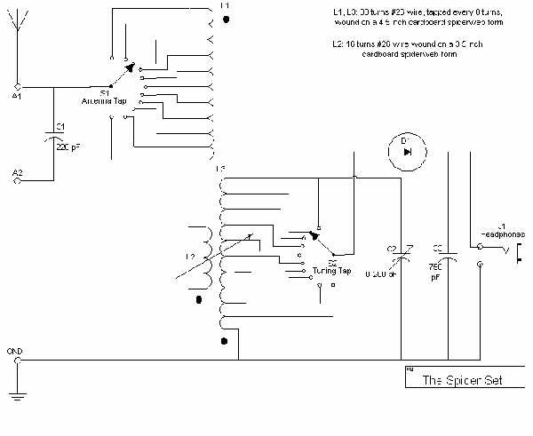
Original Schematic.
I plugged in the headphones from the old Space Spanner and gave it a listen.
PERFORMANCE:
Selectivity was broad toward the high frequency end of the band. The variable coupling between L2 and L3 helped separate the stations, but a strong station would still overwhelm its neighbors.
There were very LOUD shortwave ghosts which intruded on most of the antenna coil taps. A ferrite bead on the ground wire banished these ghosts to a tap about midway down the coil. The bead lowered the sensitivity of the set considerably. A dedicated ground banished the "haints" completely.
Reception was limited to about ten stations. The most remote station was WRVA in Richmond, VA, 50 Kw, approx. 327 miles.
Fit the Second: The Audio Transformer.
The set gave me the loudest signal when the detector was tapped 16 turns from the ground end of the tuning tank. The first improvement was the addition of an audio transformer. A trip to the local surplus electronics store produced three different types of interstage transformers. The Mil. Spec. TRW H-13 transformer gave the best performance when connected 10K - 2K. This allows the detector to tap the tank coil 4 turns from the top. (Oddly enough, the second best match was a 25 volt power transformer.) The insertion loss is barely noticeable. More stations can be heard by using the transformer than can be heard without it.
Fit the Third: Boosting Selectivity.
The original design has the antenna connection tap down the coil, making a series-tuned circuit with the coupler, and dead-ending portions of the coil. Tuning the set involved turning both the tank capacitor and the tap switch at the same time. I removed 16 turns from the antenna coil and made a tank of it and the coupler combined (a la the MRL "No. 2-A Long Distance Crystal Set"). Wow factorial! The tuning became sharp as a hummingbird whisker! The tap switch now moves the antenna up and down the coil. The best tap is 32 turns from the top. The capacitor in the detector tank now behaves as a bandspread control.
A variable capacitor was connected across the detector. This improved the volume slightly. The improvement offsets the loss from the audio transformer. If a portion of the band has a string of weak stations near each other, this capacitor will sometimes allow me to tune through them one at a time.
A wave trap was added to the antenna lead. I obtained the design from the MRL literature. The tuning capacitor is too small to cover the entire band but, as the lower part of the band has very few audible stations at my QTH, the coverage is adequate. The trap's selectivity is very sharp and allows the complete attenuation of the local (30 miles) 50 Kw stations.
The junk box contained a military TU-10-B antenna tuning unit left over from WW II (it still has the inspection tag from 1943). This became the source of a couple of the variable tuning capacitors. The ganged tuning capacitors were scavenged from old BC radios (one capacitor was made by the Defiance Co. in Defiance, OH). The mounting board (at least 80 years old) is a shelf from my Grandfather's general store.
Here is the finished (?) schematic diagram.
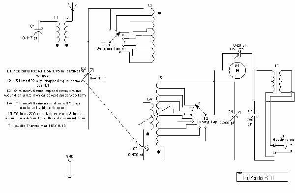
Schematic of Final Design.
Fit the Fourth: Cleanup.
The last step was to remove all the clip leads and replace them with heavier wire. I used #14 bare copper wherever possible. Heavier wire will not fit the capacitor terminals. This step alone improved performance considerably.
The set now covers a range of approximately <400 to 1500 KHz. I could move the range higher by removing more turns from the coils, but am loath to do so; I am afraid the thing will "wig out" completely, just on the eve of the Elmer Contest. In its present configuration, the set will reliably tune about twenty stations, although I have not had time to sit and really dig for more.
Since the audio transformer has an output impedance of approximately 10 - 12 K ohms, I decided to plug the rig into my stereo preamp and compare the set's fidelity to that of my digitally tuned AM/FM tuner. I unplugged one channel of the tuner and plugged in the crystal radio in its stead. The two inputs could be compared by turning the balance control left and right. Does the crystal set sound better? It emphatically does NOT!!! There is audible static, with pops, squeaks, and heterodynes produced by both units. The stereo tuner is more sensitive and produces a bit more noise, but the tone quality is the same. Neither unit, IMHO, provides more comfortable listening. The crystal set only sounds better when used with my old Allied Radio headset.
The following photo depicts the set in its present configuration.
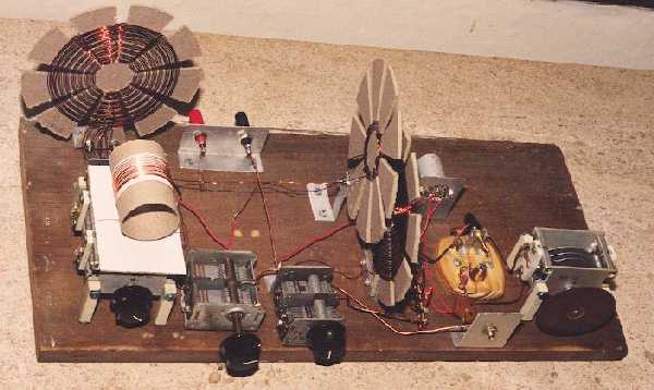
Spider Set II.
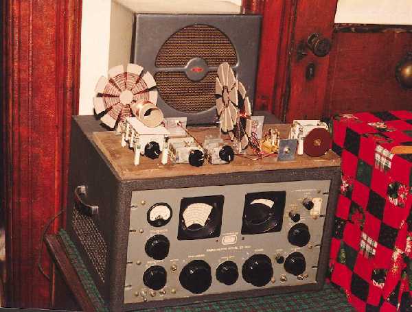
Spider Set II Sitting Atop the "Spotter" Radio.
The next photo shows the set with Mr. Tiggs, our butler. One of Tiggs' duties is to pounce on any loose wire he sees. I didn't have to teach Tiggs this chore; he just naturally takes to radio work. He doesn't like hot soldering irons, though; just can't abide 'em. Strange to say, he doesn't like cold ones, now, either.
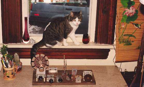
Mr. Tiggs, Superintending.