New Text
The Crystal Set Building Contest 2000/2001
"The Little Wonder"
Built by Philip Miller Tate (aka 'Ge_Whiz') 2 January 2001
General Building Category / General Class
Design
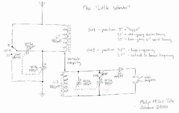
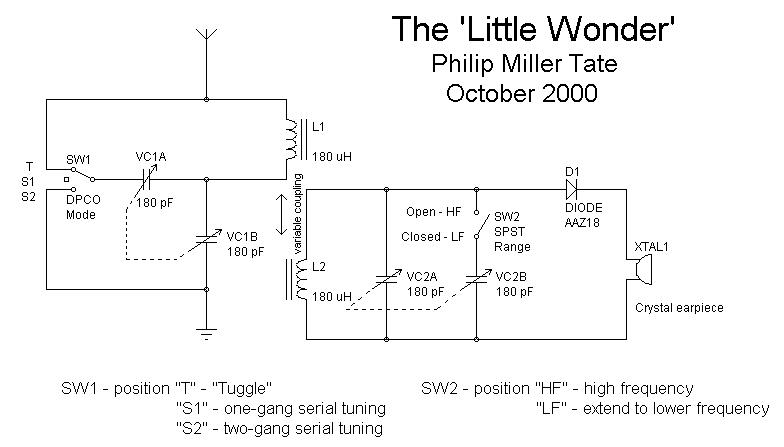
The circuit of the 'Little Wonder' is closely based on a straightforward 'loose coupler' design, but with a few enhancements (both intentional and unintentional). At the centre of the set are two commercial Litz-wound coils intended for ferrite aerial use. These were removed from their original seven-inch rods and fitted to two-inch-long ferrite pieces. In doing so, the inductance was reduced from ~250uH to 180uH which helps to extend the tuning range to high frequencies, and to overcome the effects of stray capacitance. Coverage is medium-wave only.
The tuning capacitors are both two-gang 180pF + 180pF polyfilm variables. At the front-end, the first gang is switched by a double-pole centre-off switch so that there are three different possible circuit configurations; the first is a 'Tuggle' arrangement with one gang in parallel with the coil, and the other in series with the earth. This is the most selective arrangement, and the most appropriate for short aerials. The centre setting disconnects the parallel gang to give a 180pF single-gang series-tuned arrangement which can give greater sensitivity with long aerials (at the expense of selectivity), and extended HF coverage. The third position switches the two gangs in parallel to give a series-tuned circuit with 360pF which gives a tuning range similar to the 'Tuggle' setting.
The detector stage is as simple as possible. The coil and core are identical to those in the first stage. Either one or both gangs of the second 180pF + 180pF variable capacitor can be switched in parallel to favour higher or lower frequencies. The detector is a single AAZ18 germanium diode - yeah, I know, but I still like'em - which gives good sensitivity. The output goes to a single crystal earpiece, especially chosen for its sensitivity. No combination of resistors, inductors or capacitors across the output was found to do anything but degrade the sound quality, so no extra components of this type were employed. The high impedance of the crystal earpiece obviates the need for an output transformer whilst applying minimal load on the detector.
Construction
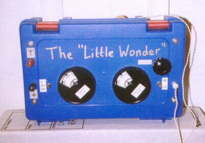
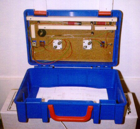
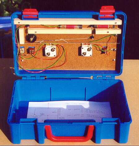
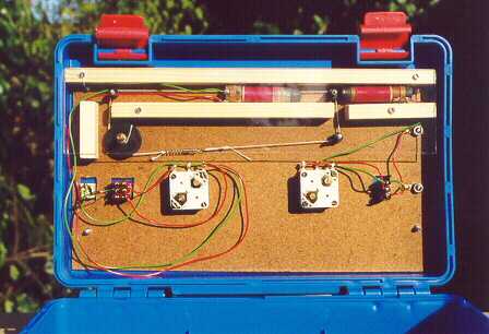
The 'Little Wonder' was built in a cheap and cheerful small plastic toolbox. The switches and earpiece socket were mounted directly on the front panel, while all the other components were built on a hardboard panel mounted directly behind the box lid to facilitate construction and provide a better appearance. The large plastic clips on the box make access to the interior very easy.
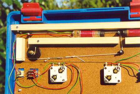
The most complicated part of the construction was concerned with the 'coupling' control. This is a rotary front-panel knob which permits the detector coil to be moved linearly with respect to the aerial circuit coil to vary the coupling between them. The coils are supported and constrained by wooden battens and a clear plastic cover, and one is moved on a simple slider mechanism employing tuning-dial cord and four pulleys. The centres of the coils can be varied between about 2.25 in. to 6.5 in. spacing, (3.5 in. being typical), which provides a useful coupling range.
Everything else is loose-wired together with the two stages well separated, and attention to keep stray capacitance to a minimum.
The entire circuitry is contained within the depth of the lid of the box. This leaves storage space in the base for the earpiece and any other accessories, and there is also room for a small stand-alone in-line wavetrap, should one be required.
Components
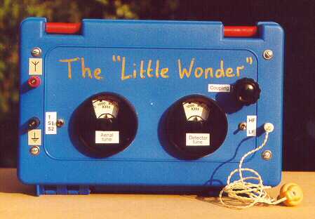
No claim can be made that any of the components used are 'vintage', unless the same 'vintage' as the constructor is permissible. The only claim is that, with the exception of the clear plastic cover of the coils, the pulleys, and the diode, everything else was purchased or otherwise obtained at substantially below retail price. The coils came from items purchased as surplus ferrite rods alone, and the quality of their appearance and construction is what inspired this design in the first place. The capacitors are from the early 1970s, and were part of 'Electronic Engineer' expansion kits purchased for a song. The case was half-price in the January sales and cost only a couple of pounds. Other components were all surplus items (including the earpiece and binding posts) or, such as the tuning cord and spring, salvaged. The aerial and earth symbol labels, the large tuning knobs, and the scales below them (which are for guidance rather than accurate) were all from the same 'Engineer' kits as the variable capacitors. Total construction cost was less than ten pounds sterling.
Performance
The final performance of this set, by comparison with its simple component design and low cost, was what earned it the name of the 'Little Wonder'. The set tunes the whole MW band from 450kHz to 1900kHz, and has a resolution (selectivity) of ~20kHz across the entire range in 'Tuggle' mode. With a sixteen-foot wire under the roof of the house, it clearly receives twelve local stations and has received at least two French DX stations. Connected to a 120-foot outdoor wire, it has received DX from Ireland, France, Spain, Italy and Sweden, although I would emphasize that it was not designed with DX reception in mind at all. The performance is such that I will probably take it with me on future holidays where I can string up an adequate aerial, as it is an ideal 'portable' set.
The overall appearance is carefully calculated to garner extra marks from those Judges who are understandably bored by all those entries with their exquisite 'antique-look' finishes, and who strongly favour the 'cheap kitsch' look that is currently so trendy throughout 21st Century Western civilization, especially in the more fashionable parts of Europe.
New images
Built by Philip Miller Tate (aka 'Ge_Whiz') 4 December 2000
General Building Category / General Class
Design
The circuit of the 'Little Wonder' is closely based on a straightforward 'loose coupler' design, but with a few enhancements (both intentional and unintentional). At the centre of the set are two commercial Litz-wound coils intended for ferrite aerial use. These were removed from their original seven-inch rods and fitted to two-inch-long pieces. In doing so, the inductance was reduced from ~250uH to 180uH which helps to extend the tuning range to high frequencies, and to overcome the effects of stray capacitance. Coverage is medium-wave only.
The tuning capacitors are both two-gang 180pF + 180pF polyfilm variables. At the front-end, the first gang is switched by a double-pole centre-off switch so that there are three different possible circuit configurations; the first is a 'Tuggle' arrangement with one gang in parallel with the coil, and the other in series with the earth. This is the most selective arrangement, and the most appropriate for short aerials. The centre setting disconnects the parallel gang to give a 180pF single-gang series-tuned arrangement which can give greater sensitivity with long aerials and further increases the HF range. The third position switches the two gangs in parallel to give a series-tuned circuit with 360pF to extend the tuning range to lower frequencies.
The detector stage is as simple as possible. The coil is identical
to that in the first stage. Either one or both gangs of the second 180pF
+ 180pF variable capacitor can be switched in parallel with it to favour
higher or lower frequencies. The detector is a single AAZ18 germanium diode
- yeah, I know, but I still like 'em - which gives good sensitivity. The
output goes to a single crystal earpiece, specially chosen for its sensitivity.
No combination of resistors, inductors or capacitors across the output
was found to do anything but degrade the sound quality, so no extra components
of this type were employed. The high impedance of the crystal earpiece
obviates the need for an output transformer whilst applying minimal load
on the detector.
Construction
The 'Little Wonder' was built in a cheap and cheerful small plastic toolbox. The switches and output socket were mounted directly on the front panel, while all the other components were built on a hardboard panel mounted directly behind the box lid to facilitate construction and provide a better appearance. The large plastic clips on the box make access to the interior very easy.
The most complicated part of the construction was concerned with the 'coupling' control. This is a rotary front-panel knob which permits the detector coil to be moved linearly with respect to the aerial circuit coil to vary the coupling between them. The coils are supported and constrained by wooden battens and a clear plastic cover, and one is moved on a simple slider mechanism employing tuning-dial cord and four pulleys. The centres of the coils can be varied between about 2.25 in. to 6.5 in. spacing, (3.5 in. being typical), which provides a useful coupling range.
Everything else is loose wired together with the two stages well-separated, and attention to keep stray capacitance to a minimum.
The entire circuitry is contained within the depth of the lid
of the box. This leaves storage space in the base for the earpiece and
any accessories, and there is also room for a small stand-alone in-line
wavetrap, should one be required.
Components
No claim can be made that any of the components used are 'vintage',
unless the same 'vintage' as the constructor is permissible. The only claim
is that, with the exception of the clear plastic cover of the coils, the
pulleys, and the diode, everything else was purchased or otherwise obtained
at substantially below retail price. The coils came from items purchased
as surplus ferrite rods alone, and the quality of their appearance and
construction is what inspired this design in the first place. The capacitors
are from the early 1970s, and were part of 'Electronic Engineer' expansion
kits purchased for a song. The case was half-price in the January sales
and cost only a couple of pounds. Other components were all surplus items
(including the earpiece and binding posts) or, such as the tuning cord
and spring, salvaged. The aerial and earth symbol labels, the large tuning
knobs, and the scales below them (which are for guidance rather than accurate)
were all from the same 'Engineer' kits as the variable capacitors. Total
construction cost was less than ten pounds sterling.
Performance
The final performance of this set, by comparison with its simple component design, was what earned it the name of the 'Little Wonder'. The set tunes the whole MW band from 450kHz to 1900kHz, and has a resolution (selectivity) of ~20kHz across the entire range in 'Tuggle' mode. With a sixteen-foot wire under the roof of the house, it clearly receives twelve local stations and has received at least two French DX stations. Connected to a 120-foot outdoor wire, it has received DX from Ireland, France, Spain, Italy and Sweden.