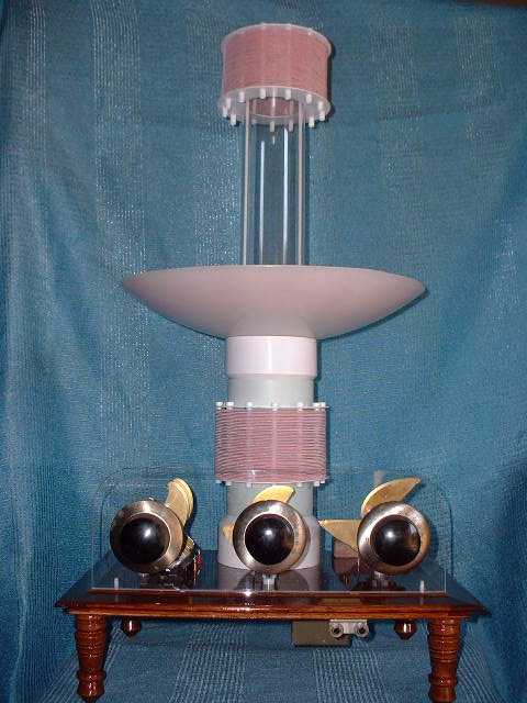
Similar coupling is provided for the wave trap coil by positioning it along its support column.
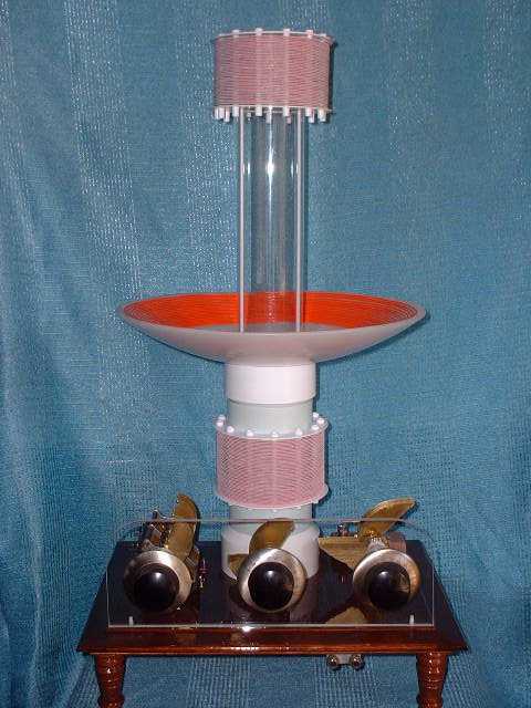
Both the detector and trap coils are wound with 420/44 Litz wire, 30% turn spaced over polystyrene coil forms. The antenna coil is #16 silver-plated, Teflon coated stranded wire, 100% turn spaced on a Lexan form. PVC tubes support the antenna and wave trap coils. The detector coil is mounted on a plexiglass tube.
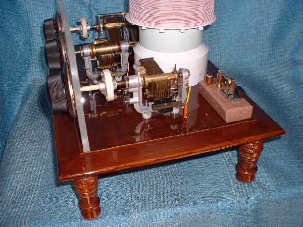
The capacitors are (NOS) Hammarlund brass types. The antenna and detector capacitors are isolated from hand capacitance and all are tuned with National “Velvet Vernier” drives.
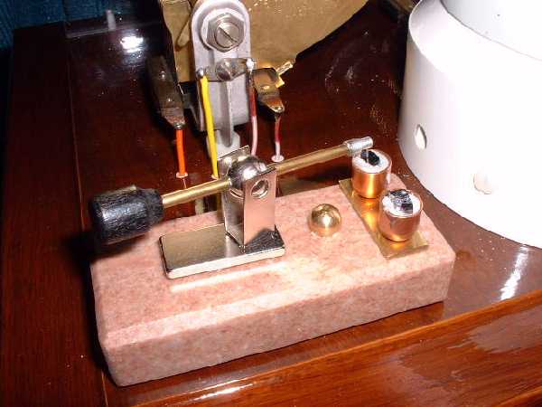
The set employs dual galena detectors, mounted on a granite base for dimensional stability. Once a sensitive spot is selected, it holds adjustment. The small brass sphere on the granite base is connected to a quick-change diode mount on the underside of the wood platform. This provides a means of rapid initial tuning before switching to the galena or experimenting with different diodes as desired. The detector arm is a Philmore unit that can be positioned anywhere on its neodymium magnet base to easily reach any crystal.
An impedance matching transformer (100k/100), for sound powered phones, is mounted on the underside with dual audio jacks for shared listening.
Nylon spacers and polystyrene tubes provide isolation for the capacitors and wire “feed through” isolation from the platform which is sealed with several coats of polyurethane.
Four, 4” legs raise the set to a comfortable visual height for the dials and provide additional isolation for the coils.
PERFORMANCE:
During the DX Contest, comparison testing with my “big set” showed Nemesis II to be very sensitive. Very weak signals were heard but the band was quite crowded. Difficulty was experienced achieving the increased selectivity expected from Litz coils.
During initial concept testing with solid wire coils, minimum coupling was within range of maximum coil separation. Litz coils require a greater separation than solid wire coils to achieve this minimum coupling. With the new coils, excessive coupling limited Nemesis’s ability to achieve a clean separation on adjacent channel stations.
Removing the ground wire restored 10 khz selectivity but the cost was lower signal strength and an increased tuning interaction between the circuits. I was somewhat surprised it received as well as it did without a ground, but attribute this to increased coil coupling.
Overall, I’m well satisfied with the set’s performance and plan to replace the support tubes with longer units to realize its full potential. It was fun to build. I now have a rather unique “Art Nouveau” crystal set for visitors to experience and enjoy. Eventually, it’s destined for my grandson to play with.