|
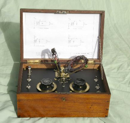
This set is based on a design found in
“The
Boy’s Book of
Wireless” written by Ernest H.Robinson and published in 1923 by Cassell
and Co.
of London.
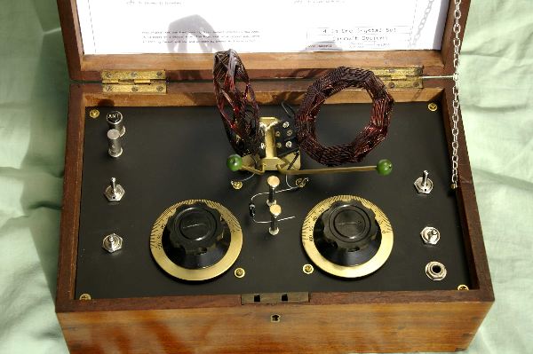
I built this set using materials
similar to
those available
to constructors in 1923. Brass knobs and fittings along with an
‘Ebonite’ front
panel give a nice antique look. Fortunately I had a good sized polished
wooden
box to build the set into. Although reasonably complex, it was all
accomplished
using the usual hand tools in my home workshop.
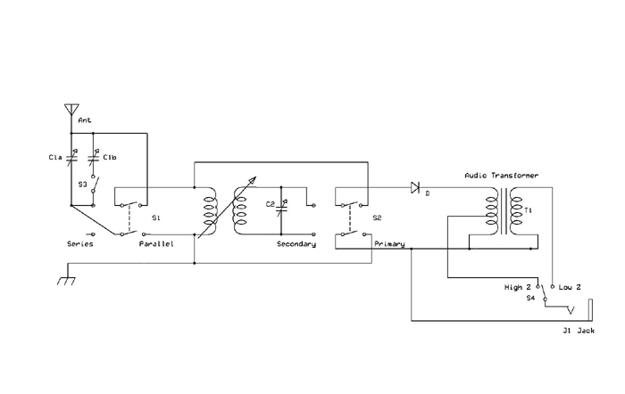
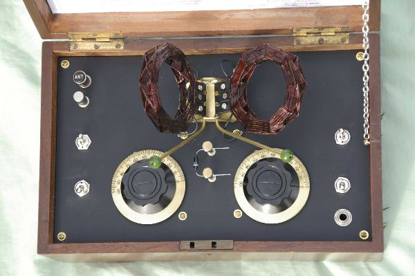
The Circuit
What makes this set
interesting is
the
ability to change the
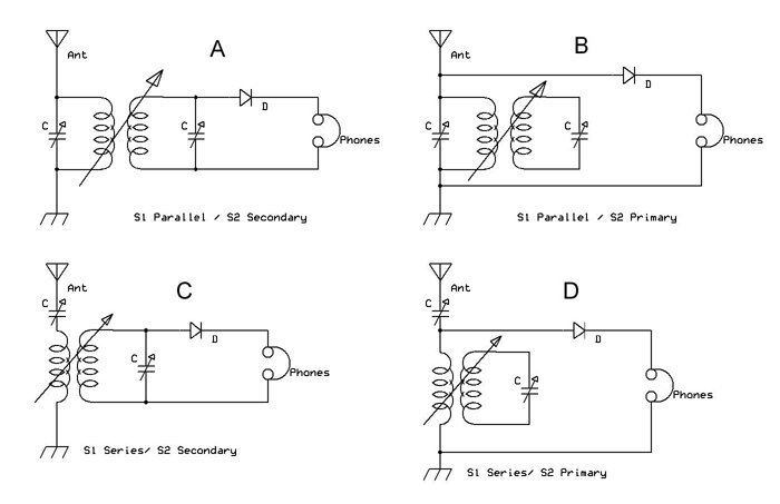
circuit to any of four configurations by the use of two switches. The
S1 allows
the selection of either a series or parallel primary (aerial) tuned
circuit and
a S2 selects the primary or secondary tuned circuit as the signal
source for
the detector. Continuously variable coupling between the two tuned
circuits
sets the band pass, and the secondary tuned circuit can also be used as
a wave
trap to notch out interfering signals.
Click
on image below for high res image for printing
The
original
circuit
showed a 1000pF variable capacitor in the aerial circuit – not easy to
find
these days – so I incorporated S3 to parallel the second gang of the
normal
415pF tuning capacitor when needed.
The other addition I made was to add
an
audio transformer to
provide a better load to the detector and also allow the use of low
impedance
phones.
Construction Hints
Front Panel
This is made from
3mm
thick acrylic sheet
measuring about
180mm by 290mm. I found some that was shiny on one side and matte on
the other.
The matte side looks like the traditional ‘Ebonite’ board used in early
radio
equipment. Acrylic sheet usually comes protected with peel-off paper on
both
sides. To prevent scratches leave this on until all the cutting and
drilling is
done.
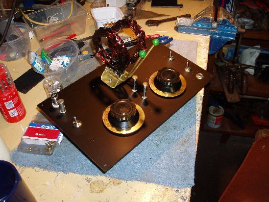
Hardware
The brass tuning
knobs
were from surplus
military equipment
and originally painted khaki. A rub with some acetone removed the
original
paint to reveal the brass scales.
The mounting posts for the diode are
made
from 25mm threaded
spacers drilled through the sides to take the diode wires. Thumb screws
are
from the junk box, as are the antenna and earth terminals
Toggle switches are DPDT
from
Tandy. The
original design
used miniature knife switches. Nice if you can find any.
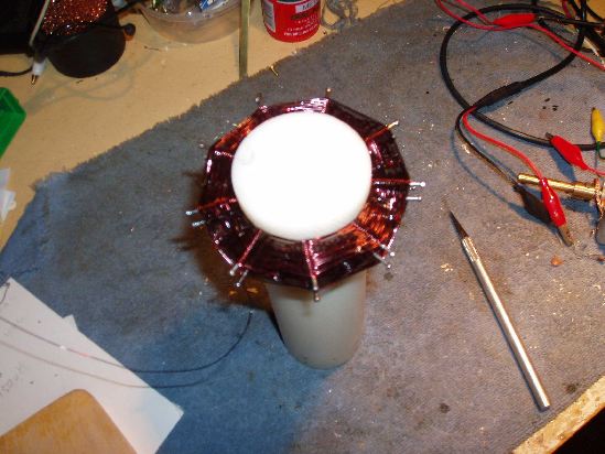
Coils
The coils are basketweave type wound on a
50mm former. I
used a piece of plastic rod but a turned piece of wood would do fine.
Draw two
parallel lines spaced 10mm apart around the circumference of the
former. Drill
and push fit 9 pairs of small nails evenly spaced around the two lines.
Smear the former and nails with a
little oil
to help when
removing the finished coil.
I wound the coils with a 1 up 1 down
pattern. ( see
basketweave coil winding elsewhere on this website)
The exact number of turns is hard to count
due to the cross-overs, but any one panel counts 12 turns high. Coil
inductance
measures about 200uH. Best to wind too many turns then remove some
later. Apply
clear nail polish to the cross-overs and let dry. Ease out the nails
and gently
slide the coil from the former. Apply a generous coat or two of varnish
to hold
the coil together. Glue the coils to acrylic squares to mount on the
coil
holder.
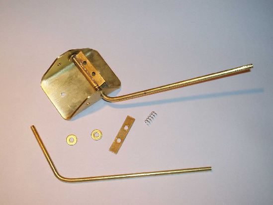
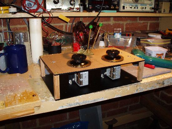
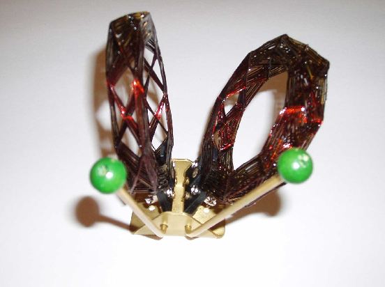
Coil Holder
The photograph shows the construction pretty
well. Brass
stock is from a hobby shop. The base is drilled then bent up in a vyce.
Make
the front holes in the base a little oversize to allow the bends in the
arms to
slide through. The springs come from ball point pens. Knobs are wooden
beads.
Audio transformer
The audio transformer is a common type used
to match 8 ohm
loudspeakers to a 100 volt line in public address systems. It has
primary taps
of 2k, 4k, 8k, 16k and 32k. I put the detector diode on the 32k tap and
the
high impedance phones on the 4k tap. Experiment and see what works best
with
your detector and phones. Low impedance phones go to the 8 ohm
secondary.
Performance
Make no mistake;
though
this set was
designed in 1923 it is
a real performer. With an adequate aerial and earth and using a good
germanium
diode detector it will drag in DX stations from around the country.
John Hassell
VK6JAH
jah12@bigpond.com
|