|
Introduction:
This is a description of the procedure I
performed trying to make a high-impedance-high-sensitivity earphone
set. The
idea was to combine the advantages of high
impedance vintage phones with the high sensitivity of an
balanced-armature
construction. I was more than satisfied with the results and I would
like to
share my experience with other DX enthusiasts.
I’ve have several DLR-5 earphones and
I
decided to rewind the spools of one pair.
First I tested their
characteristics and here
they are (per one element):
DC-resistance..............................27
Ohms
AC-impedance at 1
kHz............280 Ohms
Sensitivity at 1
kHz..................0.13
picoW
It wasn’t easy at all, but I am sure, with the
patience and enthusiasm you can also do this.
Before you
start,
keep in mind:
Don’t
rush, take your time!
Don’t
panic if something goes wrong! Almost
everything is reparable (see also the section troubleshooting).
Keep
dust and small particles away.
Control
every step as it is done
Never
solder or de-solder the coil contacts
with the permanent magnet in place because of the strong alternating
magnetic
field of the soldering iron.
Use
magnifying goggles.
Part 1 – Disassembling The
Element
At fig.1 you can see the front and rear of the
original DLR-5 earpiece, in- and outside the housing.
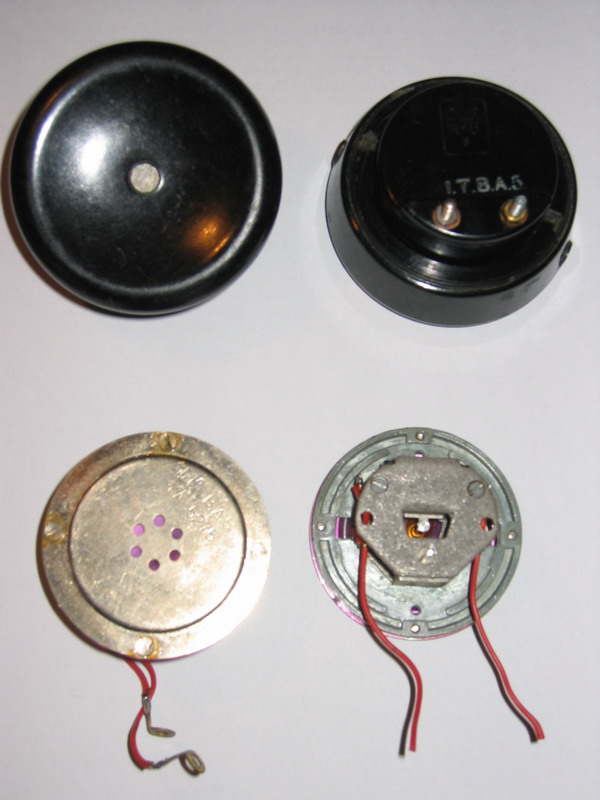
Fig.
1
When
taking the element out, you should better
unscrew the contact screws than desolder the leads in such a small
space and
near the magnet.
After
loosen the three screws on the top, first
remove the magnet and then the upper plate of the magnet unit. It is
very
difficult to work within the strong magnetic field and there is the
risk of
damaging the armature.
Pull the
leads out of the eyelet of the lead
holder. Do not desolder the leads from the coil yet! The ends are wound
around
the coil contact plate.
Unscrew
the tiny nut from the drive rod using
fine but strong forceps like those shown at Fig. 2. (Bent microsurgical
or the depilation
forceps).
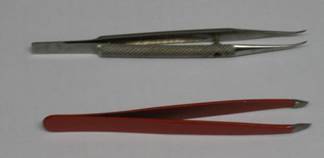
Fig 2
Remove
the coil, with the armature still
inside straight upwards, to avoid damaging the drive rod.
Bottom
plate of the magnet unit has to be
removed only if you should clean it from the hardened varnish. It is
important
to clean it because the varnish can later interfere with the
reassembling the
coil, damaging the wire, or can break and the particles can fall into
the
diaphragm space or between the armature and the coil.
The
diaphragm, drive rod and the second nut
you should leave in place. Try not to touch the lower nut, because it
determines the central position of the armature.
All
parts
are shown at the fig. 3.
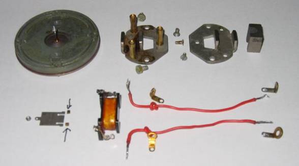
Fig 3
Important: the two tiny ”U”-shaped parts,
marked with the arrows at the photograph (fig 3), are the only two
fixation
points of the armature, and they also determine the distance between
back end
of the armature and the poles of the magnet unit. Remember the position
of the
two pieces before removing the armature from the coil form and don’t
loos them!
Part 2 –Preparing The Coil Form
At
the coil form, you see two contact-plates
with lead contact and coil-wire contact each.
Using two
pairs of tong, as shown at fig. 4,
bend them straight or a few degrees further. Don’t hold the coil; the
form can break
by bending!
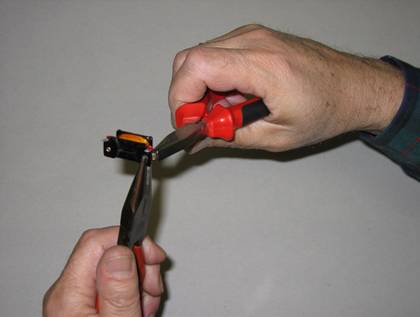
Fig 4
Now
remove the original wire. (You can keep
it, just in case you decide to undo the whole job!) ) and clean the
coil form
from the varnish. Also clean the soldering points.
Remove
the isolation from the contact plates
and polish them as well as the edges of the form with the fine
sand-paper (#
360 or higher). The whole inner side should be smooth and without any
obstacles, otherwise it could catch and break the delicate wire later.
Fig.5
shows the form ready for winding.
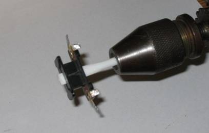
Fig 5
Part 3 – The Wire
The idea of the whole project was to get
higher impedance and that means as much turns as possible. To achieve
that, you
need the thinnest wire you can get and maximum space for it.
The
wire
I used was enamel coated 0.05 mm from
a reed-relay activating coil. Another way is to order it via Internet.
I
ordered some by CONRAD (www.conrad.nl),
order nr. 60 75 09-06, cost 3.55 Euro
+p.p. One spool (cc 1500 m) is enough for pair of phones. Anyway, the
wire must
be solderable. The wires I use are shown at fig. 6. Available space is
limited
by the mounting rods, as shown at fig. 7. You can not stuff the whole
form
because of the clearance of 18 mm between the two mounting rods. The
drawing
also shows how you have to bend the contacts from their original
position
(marked 1.) to the temporary winding position (marked 2.). After winding, bend them back to the position 1.
See also fig. 4! Mark 3. is available
wire-space.
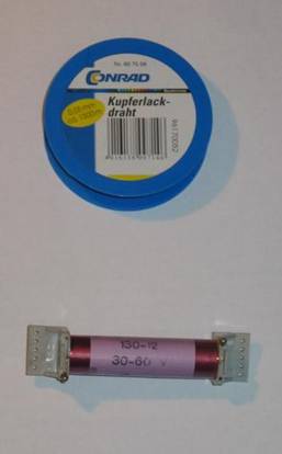
Fig. 6
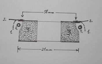
Fig. 7
Part 4 – Winding
When
everything is ready, begins the real work
and excitement!
I
have
recently got a winding device for old
8mm films, shown at fig. 8.
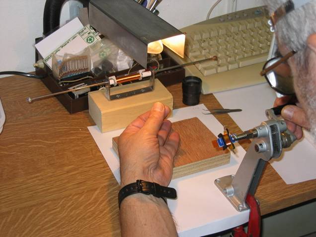
Fig 8
You
can
also use a hand-drill fixed in the
claws, as I did for years (fig. 9).
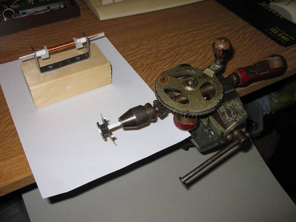
Fig 9
It
is
very important to centre the form
perfectly, otherwise the windings can escape over the form edge.
Besides wearing magnifying goggles, do have a
bright spot light and put a white paper under the coil and the wire. It
is
important to see the wire and how you feed it. You can see better by
looking
with only one eye! Choose the direction
of winding so that the wire comes from upside the coil. The
source-spool must
also spin easily, without any resistance. With
your left hand, rested on the confortable height, you
lead the
wire, organise it within the coil, and keep it under a slight tension.
See fig
8. Try to organise the windings as good as possible, don’t make
criss-cross, it
takes unnecessary space. Try first a few layers to get some experience
and to
feel the maximal tension before breaking the wire.
Than cut
a few small strips of adhesive tape.
You shall need them to fix the wire at the coil if you have to make a
break for
any reason.
Secure the start by making a threefold loop of
4-5 cm and twist it. Bend it around the soldering contact (do not cut
it!) and
make the first few turns with such a strengthened twisted part and then
continue with single wire layers. Do the same with the end!
Mark at the paper every 100 turns if you do
not have automatic counter. You will later want to know how many turns
you have
put into the coil. You can calculate the total number of wire turns by
multiplying the number of drill-handle turns with the turn-ratio.
After
finishing the winding, solder the ends
and protect the windings with a 7mm wide strip of thin elastic adhesive
tape,
or a thin layer of a transparent nail-polish.
Control the clearance for the two mounting
rods, it should be 18 mm. Also control with the Ohm-meter if the
contacts are
good. The DC resistance should be between 1500 to 2000 Ohms.
Part 5 –
Reassembling The Element
Clean and
check all parts prior to reassemble
the unit in opposite sequence. That means the bottom plate first. Slide
the
armature in the coil with small hole facing the contact-side. Than put
the coil
(with the armature inside and the two small fixation
“U”-shaped parts in place), vertically into
the bottom plate so that the poles fit into the special grooves on the
coil
form. The drive rod must pass through the small hole of the armature,
and two
fixation pieces must lay at the pole of the magnet unit bottom plate.
Now
put
back the upper nut of the drive rod
and fasten the armature.
It
is of
crucial importance to check if the
armature is free and at equal distance on both sides within the central
slit of
the coil form!!! If not – adjust with
both nuts and tighten it. Remember that the vibrations of the armature
have to
be transferred to the drive rod and finally to the diaphragm. When you
put back
the upper plate, adjustment would be very difficult, if not impossible.
When
everything is OK, put back the upper
plate so that the poles fit into the upper grooves of the coil form.
Put the
screws back, but don’t fasten them yet. First slide the magnet back and
than
fasten the screws.
Pull the
leads through the eyelet of the
lead-holder and check once again if the armature is at central
position. If you
look through the coil against the light, you should see equal spacing
between
the armature and the poles of the magnet unit. Also check if the lead
contacts
are not touching the adjacent metal parts.
Now
put
back the contact-screws and fix the
element into the housing.
Connect
the flexible cable and the head-band
and...finally you’ve got it! (Fig 10)
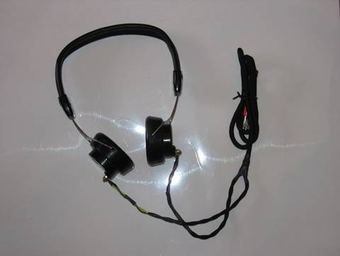
Fig 10
Part 6 – Testing The Phones
To
check
the presumed characteristics you can
test the phones or simply compare with another set you have.
I rewound two elements and tested the
headphone-set using the following instruments: PHILIPS LF Generator PM
5100,
PHILIPS dual oscilloscope model PM 3207,
Digital AVO-meter Conrad Electronics M830B and analogue
Velleman Multitester 40000 Ohms/V.
There are
many procedures described on the Web
to test the AC impedance and the sensitivity. I
applied the one described by Dick Kleiert, with a small
variation: for
R1 I used 50 kOhms instead of 10 kOhms for better reading of the input
voltage
(200 mV).
Here are the
results:
- Windings
per
element................5300 + 5000
DC Set
resistance...................................3870 Ohms (2050 + 1840 )
AC Impedance at 1
kHz.......................56000 Ohms (pair)
Threshold sensitivity
at 1
kHz...........0.00028 picoW (pair)
The
term
“threshold sensitivity” has to
describe that I just was able to hear the 1 kHz signal in the compete
silence.
Of course, to understand the speech or music, you need more input
energy.
Part 7 –
Troubleshooting
In
spite
of all the attention and care there
is always something what can go wrong. Here are some situations, and
how you
can manage them:
Problem:
One
of the two “U”- shaped armature-fixation parts jumps off and you can
not find
it any more.
Solution:
Take
a 0.2 mm thin sheet of a non-magnetic metal and cut a strip 2mm wide
and 5 mm
long. Bend it around 0.6 mm, (that is the thickness of the armature) in
a
U-shape.
Problem:
Coil
form brakes.
Solution:
Cut
a piece 3 x 8 mm of thin (0.15-0.2 mm) pertinaks or similar hard non-
metallic
material and glue the patch from inside (wire-side) with cyanacryl glue.
Problem:
The
wire breaks.
Solution:
Fix the last layer at the
coil with
the
piece of adhesive tape and twist both broken wire-ends together. Solder
the
joint, cut it off to the length of about 2 mm and continue winding.
It’s no
need of any isolation (occupies the precious space), just cover it with
the
next layer of wire.
Problem:
You
loos the tiny nut of the drive rod.
Solution:
Try
to get one by the watch-maker or by an optician, or in some hobby-shop.
Take
the element with you to check the size.
Maybe it is a good idea to have one extra
(third) phone-element, just for the spare parts or to try again by
serious problems.
Part 8 – Epilogue
I
am
aware of the fact that my effort and the
result is not enough for a serious DX-work, but it is fun to try
something new.
Maybe I made some mistakes, in approach or by the testing. If anyone
does or
has done something similar, I would be grateful for any comments,
corrections
or confirmations. Also if you want some more information, mail me at d.mom@planet.nl
And
finally, fig. 11 shows my hobby-corner
where everything has been done.
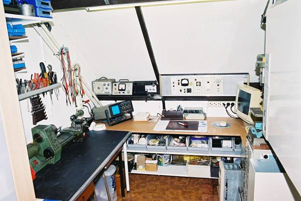
Fig 11
Good luck,
Dejan
Rotterdam, October 2005
|